In ERW pipes, the highest risk isn't the steel body—it's the longitudinal weld. ERW pipes offer excellent dimensional accuracy and high production efficiency, but flaws like "lack of fusion" are planar, invisible from the surface, and can pass a standard hydrostatic test, only to fail under operating pressure.
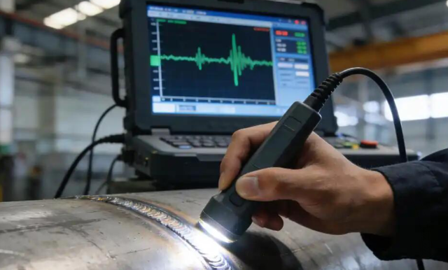
This is why 100% Ultrasonic Testing (UT) is mandatory in a modern ERW production line.
Defect Types in ERW Pipes
Welding defects affect the pipe in two main ways:
● Planar Defects (Cracks, Lack of Fusion): Flat discontinuities that cause severe stress concentration under load. They are the primary cause of low-stress brittle fractures in weld seams.
● Volumetric Defects (Pores, Slag): While less likely to cause immediate cracking, they reduce the effective cross-sectional area and strength of the weld.
Four UT Applications in ERW Production
UT is used at four critical stages to catch defects before shipment:
1. In-line UT of the steel strip (before forming).
2. In-line UT of the weld seam (immediately after welding and flash removal).
3. Off-line UT of the weld seam (after hydrostatic testing and bevelling).
4. Manual UT of the pipe ends (to cover blind zones).
In-line UT of the Steel Strip
Before forming, the strip must be scanned for laminations. The system uses dual-element transducers coupled via a water film to detect discontinuities parallel to the plate surface. Because the plate edges will eventually form the weld seam, standards mandate 100% coverage of the edges, usually by increasing the number of transducers.
In-line UT of the Weld Seam
Performed immediately after welding and flash removal, this stage has two components:
● Flash Verification: A-scan or B-scan techniques verify the internal burr is fully removed. (B-scan provides a real-time, intuitive visual representation of the internal weld profile).
● Defect Detection: An angled probe introduces the sound wave, which refracts at the pipe surface to generate shear waves inside the pipe wall to detect welding defects. Because the pipe remains at a high temperature, high-temperature-resistant transducers are used via localized water immersion.
Off-line UT and Pipe-End Inspection
Automated UT scans the full weld length after hydrostatic testing to detect defects in the weld and heat-affected zone (HAZ). However, automated systems have "blind zones" at the pipe ends. Therefore, a supplementary manual UT scan is required. Pipe-end inspection covers the weld seam, as well as laminations, axial, and circumferential defects in the base metal.
Selection of UT Process Parameters
Automated inspection (wheel-type or immersion) offers high speed, but manual inspection is needed for precise defect sizing. To ensure accurate detection, engineers must calibrate key parameters:
Refraction Angle Selection
UT of ERW welds uses longitudinal-wave oblique incidence to generate transverse waves. Two requirements are fundamental:
1. Generate pure transverse waves in the base metal and weld.
2. Ensure the transverse-wave beam scans the inner surface of the pipe.
The lower limit for the refraction angle is 33.2°. The upper limit varies based on the inner/outer radius ratio (r/R). A 45° refraction angle at the inner wall provides high sensitivity for surface-breaking defects.
Inspection Frequency Selection
The frequency range spans 0.5–10 MHz. For ERW pipes, 2.5–5 MHz is the practical sweet spot. Why?
● Sensitivity: Increasing frequency detects smaller defects and improves resolution.
● Beam Directivity: Higher frequencies mean shorter wavelengths and better beam directivity for precise defect localization.
● Trade-off: Too high a frequency increases near-field length and sharply increases signal attenuation (scattering and absorption). Because ERW base metal and HAZ have a fine grain structure, 2.5–5 MHz provides the best balance.
Reference Blocks
Standards like
API 5L and GB/T 9711 require the use of reference blocks containing artificial reflectors to calibrate the UT machine. Depending on the specific standard and inspection area, these reflectors could be a 3.2 mm diameter through-hole (for pipe body) or an N5/N10 notch (for the weld seam). The echo from these reflectors establishes the 100% reference level for evaluating actual weld defects.
Conclusion
Relying solely on a hydrostatic test is not enough for high-quality ERW pipes. By combining 100% in-line UT, supplementary manual pipe-end UT, and correctly calibrated parameters, manufacturers can guarantee weld integrity that meets API 5L standards.
Related topics
● ERW Steel Pipe Manufacturing Process
● NDT for ERW Pipe Welds: What Buyers Need to Check
● Hydrostatic Test of ERW Pipe – What it can and cannot detect.
● ERW Pipe Thickness Chart & Sizing Guide – Standard dimensions and weight data.
● ERW Steel Pipe Quality Control & Inspection Methods – Learn how NDT fits into the complete quality control process.
 sales@hu-steel.com
 English
 Español