sales@hu-steel.com
 English
 Español
ERW (Electric Resistance Welded) pipe, also known as high-frequency resistance welded steel pipe, is a steel pipe formed by continuous forming of hot-rolled steel strip (coil), using the skin effect and proximity effect of high-frequency current to heat the edge of the steel plate, and welding it under pressure.
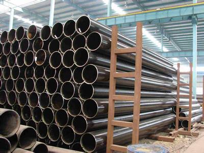
ERW (electric resistance welded) pipes & tubes are available in a wide range of sizes, typically from 1/2" to 24" in diameter. The wall thickness of these pipes varies, with common thicknesses ranging from 2mm to 12.7mm.
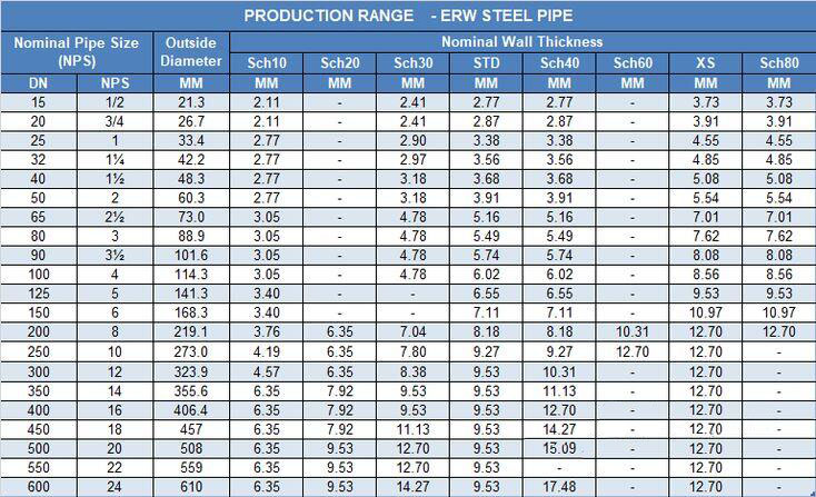
This table only lists the commonly used wall thickness grades (STD / Sch 40, XS / Sch 80) for carbon steel ERW pipes, suitable for quick selection or preliminary design reference. For wall thickness data from Sch 10 to XXS, please refer to the "Complete Dimension Table" below.
This table provides wall thickness data for the entire range of carbon steel pipes (applicable to ERW and seamless) from Sch 10 to XXS, based on ASME B36.10M, suitable for detailed engineering design or specification verification. For quick reference of commonly used wall thicknesses, please refer to the quick lookup table above.
| DN | NPS | Wall Thickness (mm) | Sch 10 | Sch 20 | Sch 30 | Sch 40 / STD | Sch 60 | Sch 80 / XS | Sch 100 | Sch 120 | Sch 140 | Sch 160 | XXS |
|---|---|---|---|---|---|---|---|---|---|---|---|---|---|
| 15 | 1/2" | 21.3 | 2.11 | - | 2.41 | 2.77 | - | 3.73 | - | - | - | 4.78 | 7.47 |
| 20 | 3/4" | 26.7 | 2.11 | - | 2.41 | 2.87 | - | 3.91 | - | - | - | 5.56 | 7.82 |
| 25 | 1" | 33.4 | 2.77 | - | 2.90 | 3.38 | - | 4.55 | - | - | - | 6.35 | 9.09 |
| 40 | 1½" | 48.3 | 2.77 | - | 3.18 | 3.68 | - | 5.08 | - | - | - | 7.14 | 10.15 |
| 50 | 2" | 60.3 | 2.77 | - | 3.18 | 3.91 | - | 5.54 | - | - | - | 8.74 | 11.07 |
| 80 | 3" | 88.9 | 3.05 | - | 4.78 | 5.49 | - | 7.62 | - | - | - | 11.13 | 15.24 |
| 100 | 4" | 114.3 | 3.05 | - | 4.78 | 6.02 | - | 8.56 | - | 11.13 | - | 13.49 | 17.12 |
| 150 | 6" | 168.3 | 3.40 | - | - | 7.11 | - | 10.97 | - | 14.27 | - | 18.26 | 21.95 |
| 200 | 8" | 219.1 | 3.76 | 6.35 | 7.04 | 8.18 | 10.31 | 12.70 | 15.09 | 18.26 | 20.62 | 23.01 | 22.23 |
| 250 | 10" | 273.1 | 4.19 | 6.35 | 7.80 | 9.27 | 12.70 | 15.09 | 18.26 | 21.44 | 25.40 | 28.58 | 25.40 |
| 300 | 12" | 323.9 | 4.57 | 6.35 | 8.38 | 10.31 | 14.27 | 17.48 | 21.44 | 25.40 | 28.58 | 33.32 | 25.40 |
| 350 | 14" | 355.6 | - | 6.35 | 7.92 | 11.13 | 15.09 | 19.05 | 23.83 | 27.79 | 31.75 | 35.71 | - |
| 400 | 16" | 406.4 | - | 6.35 | 7.92 | 12.70 | 16.66 | 21.44 | 26.19 | 30.96 | 36.53 | 40.49 | - |
| 450 | 18" | 457.0 | - | 6.35 | 7.92 | 14.27 | 19.05 | 23.83 | 29.36 | 34.93 | 39.67 | 45.24 | - |
| 500 | 20" | 508.0 | - | 6.35 | 9.53 | 15.09 | 20.62 | 26.19 | 32.54 | 38.10 | 44.45 | 50.01 | - |
| 600 | 24" | 610.0 | - | 6.35 | 9.53 | 17.48 | 24.61 | 30.96 | 38.89 | 46.02 | 52.37 | 59.54 | - |
The standards and ranges listed above are for design reference. For final wall thickness selection, always consult the detailed specification tables on this page and confirm with your project’s design code.
|
Application |
Reference Standard for Design |
Typical Wall Thickness Range |
|
Low-pressure water/gas lines |
ASTM A53 SCH 40 |
2.77 mm ~ 8.18 mm |
|
Oil/gas transmission |
API 5L Gr.B |
3.91 mm ~ 12.70 mm |
|
High-pressure industrial pipelines |
API 5L X42/X52 |
6.0 mm ~ 15.0 mm |
|
Building, bridge, mechanical structures |
ASTM A500 |
1.0 mm ~ 22.0 mm (OD: 21.3mm~660mm) |
|
Building scaffolding |
GB/T 3091 |
2.0 mm ~ 4.0 mm |
Example: For a 6-inch (168.3mm OD) ERW pipe under 10MPa pressure, with S=138MPa and E=0.85, the minimum wall thickness is approximately 7.4mm.
Theoretical weight per meter for common ERW pipe schedules. Based on carbon steel density (7.85 g/cm³).
| NPS (inch) |
Outer Diameter (mm) |
SCH 5 | SCH 10 | SCH 40 / STD | SCH 80 / XS | ||||
|---|---|---|---|---|---|---|---|---|---|
| WT (mm) | Wt (kg/m) | WT (mm) | Wt (kg/m) | WT (mm) | Wt (kg/m) | WT (mm) | Wt (kg/m) | ||
| 1/2" | 21.3 | 1.65 | 0.81 | 2.11 | 1.01 | 2.77 | 1.29 | 3.73 | 1.62 |
| 3/4" | 26.7 | 1.65 | 1.03 | 2.11 | 1.30 | 2.87 | 1.71 | 3.91 | 2.20 |
| 1" | 33.4 | 1.65 | 1.31 | 2.77 | 2.12 | 3.38 | 2.54 | 4.55 | 3.29 |
| 1¼" | 42.2 | 1.65 | 1.93 | 2.77 | 3.15 | 3.68 | 3.48 | 4.85 | 4.47 |
| 1½" | 48.3 | 1.65 | 1.93 | 2.77 | 3.15 | 3.68 | 4.05 | 5.08 | 5.41 |
| 2" | 60.3 | 1.65 | 2.42 | 2.77 | 3.98 | 3.91 | 5.44 | 5.54 | 7.48 |
| 2½" | 73.0 | — | — | — | — | 5.16 | 8.63 | 7.01 | 11.41 |
| 3" | 88.9 | 2.11 | 4.58 | 3.05 | 6.54 | 5.49 | 11.29 | 7.62 | 15.27 |
| 3½" | 101.6 | 2.11 | 5.25 | 3.05 | 7.52 | 5.74 | 13.77 | — | — |
| 4" | 114.3 | 2.11 | 5.25 | 3.05 | 7.52 | 6.02 | 16.07 | 8.56 | 22.32 |
| 5" | 141.3 | 2.77 | 9.50 | 3.40 | 11.74 | 6.55 | 21.77 | 9.53 | 30.97 |
| 6" | 168.3 | 2.77 | 11.47 | 3.40 | 14.04 | 7.11 | 28.25 | 10.97 | 42.56 |
| 8" | 219.1 | 2.77 | 14.99 | 3.76 | 20.25 | 8.18 | 42.55 | 12.70 | 64.64 |
| 10" | 273.1 | — | — | — | — | 9.27 | 60.29 | 15.09 | 94.79 |
| 12" | 323.9 | — | — | — | — | 10.31 | 79.62 | 17.48 | 128.07 |
| 14" | 355.6 | — | — | — | — | 11.13 | 94.26 | — | — |
| 16" | 406.4 | — | — | — | — | 12.70 | 122.00 | — | — |
| 18" | 457.2 | — | — | — | — | 14.27 | 153.00 | — | — |
| 20" | 508.0 | — | — | — | — | 15.09 | 183.00 | — | — |
| 24" | 609.6 | — | — | — | — | 17.48 | 248.00 | — | — |
The weight calculation of ERW steel pipe is usually based on the theoretical weight formula for steel pipe. Since ERW steel pipe is a welded pipe, its calculation is the same as that of seamless steel pipe, both calculated based on the principle of unfolding a round pipe into a steel strip.
0.02466 = Density coefficient of steel pipe material, applicable to ordinary carbon steel, density is taken as 7.85 g/cm³
Weight Calculation Example: For a 6-inch ERW pipe (OD=168.3mm) with wall thickness 7.11mm:
W = 0.02466 × 7.11 × (168.3 - 7.11) = 28.26 kg/m
|
Size Classification |
Outer Diameter Range |
Wall Thickness Characteristics |
Main Applications |
|
Small Diameter Pipe |
21.3 - 114.3 mm |
Thinner, typically 2.0 - 6.0 mm |
- Water and gas pipelines in buildings - Branch pipes for fire sprinkler systems - Furniture and scaffolding structures - Mechanical parts |
|
Medium Diameter Pipe |
114.3 - 323.9 mm (Approx. 4 - 12 inches) |
Moderate, typically 4.0 - 12.7 mm |
- Urban water supply and heating networks - Oil and gas gathering and transmission pipelines - Building structural support columns - General industrial fluid transportation |
|
Large Diameter Pipe |
323.9 - 610 mm (Approx. 12 - 24 inches) |
Thicker, up to 19.1 mm |
- Long-distance oil and gas trunk pipelines - Marine engineering and structural pile foundations - Large-scale water conservancy and industrial circulating water systems - Municipal main pipeline network |
ASTM A53 is a pressure/fluid standard, suitable for conveying steam, water, gas, and air in industrial pipeline systems.
Selecting the right ERW pipe wall thickness is essential for balancing safety, performance, and cost. Use the charts above for quick reference, and always consult relevant design standards (ASME B36.10M, API 5L, ASTM A53) for your specific project requirements. For customized solutions or technical support, contact our engineering team.
You may be interested in the following technical documents regarding steel pipe specifications and dimensions:
● Carbon Steel ERW Pipe Grade & Specification
Related information
Copyright @2017 Hunan Standard Steel Co.,Ltd and Husteel Industry Group All Rights Reserved