sales@hu-steel.com
 English
 Español
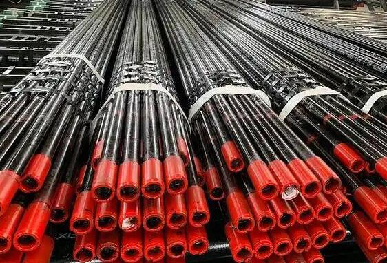
API Tubing refers to steel pipes manufactured according to American Petroleum Institute (API) standards, used in oil and gas wells to transport produced hydrocarbons or injected fluids. Unlike casing pipe—which is a permanent structural component—tubing is installed inside the casing and serves as the conduit through which oil and gas flow from the reservoir to the surface.
Tubing must be strong enough to withstand production loads and workover operations, and correctly sized to support expected production rates. Selecting tubing that is too small restricts flow and reduces well economics. Tubing that is too large, however, not only costs more but also affects the overall casing design—larger tubing may require larger casing, increasing well construction costs.
Casing and tubing serve different roles in well construction:
| Aspect | Casing | Tubing |
| Function | Supports wellbore, isolates formations, protects groundwater | Transports oil and gas from reservoir to surface |
| Installation | Cemented in place, permanent structure | Run inside casing, can be replaced |
| Diameter | Generally larger (≥ 4-1/2″) | Generally smaller (≤ 4-1/2″) |
| Load Type | External pressure, collapse, tension | Internal pressure, corrosion, tension |
△ A common rule of thumb: 4-1/2 inch (114.3 mm) outer diameter is the dividing line. Sizes equal to or smaller than 4-1/2″ are typically tubing; sizes larger are casing. ▶ For complete casing dimensions and weight data, refer to our [OCTG Casing Size Chart].
The choice of tubing size and grade directly affects well performance. Key factors to consider:
1. Expected Production Rate
Higher flow rates require larger tubing to minimize friction loss.
Too small a diameter restricts flow and limits production.
Too large a diameter may slow fluid velocity, affecting lift efficiency.
2. Well Depth and Pressure
Deeper wells require higher strength grades to support the tubing string weight.
High-pressure wells need thicker walls and higher collapse resistance.
3. Downhole Environment
Sour service (H₂S): Use L80 or higher sour-resistant grades.
Corrosive environment (CO₂): Consider 13Cr or corrosion-resistant alloys.
Standard conditions: J55, N80, or P110 grades are typically sufficient.
▶ For a detailed comparison of these grades, see our [J55 vs N80 vs P110 Casing Performance Comparison Guide].
4. Tubing and Casing Clearance
Tubing outer diameter must allow sufficient clearance inside the casing for installation and production equipment (e.g., pumps, packers).
The following table lists common API tubing sizes, weights, and grade availability.
△ Notes:
Plain End (P): Tube ends without upsetting, used with non-upset connections.
Non-Upset (N): Tube ends are not thickened; standard for most tubing.
External Upset (E): Tube ends are thickened externally for stronger connections.
Premium connections are available upon request for high-pressure or critical applications.
|
Outside Diameter
|
Wall Thickness
|
Weight
|
Grade and Upset Type*
|
|||||||||
|
Non-Upset T&C
|
External Upset T&C
|
|||||||||||
|
in.
|
mm
|
in.
|
mm
|
lb/ft
|
kg/m
|
lb/ft
|
kg/m
|
J55
|
L80
|
N80
|
C90
|
P110
|
|
2-3/8
|
60.32
|
0.167
|
4.24
|
4.00
|
5.95
|
-
|
-
|
PN
|
PN
|
PN
|
PN
|
-
|
|
0.190
|
4.83
|
4.60
|
6.85
|
4.70
|
6.99
|
PNU
|
PNU
|
PNU
|
PNU
|
PNU
|
||
|
0.254
|
6.45
|
5.80
|
8.63
|
5.95
|
8.85
|
-
|
PNU
|
PNU
|
PNU
|
PNU
|
||
|
0.336
|
8.53
|
7.35
|
10.94
|
7.45
|
11.09
|
PU
|
-
|
PU
|
PU
|
-
|
||
|
2-7/8
|
73.02
|
0.217
|
5.51
|
6.40
|
9.52
|
6.50
|
9.67
|
PNU
|
PNU
|
PNU
|
PNU
|
PNU
|
|
0.276
|
7.01
|
7.80
|
11.61
|
7.90
|
11.76
|
-
|
PNU
|
PNU
|
PNU
|
PNU
|
||
|
0.308
|
7.82
|
8.60
|
12.80
|
8.70
|
12.95
|
-
|
PNU
|
PNU
|
PNU
|
PNU
|
||
|
0.340
|
8.64
|
9.35
|
13.91
|
9.45
|
14.06
|
-
|
PU
|
-
|
PU
|
-
|
||
|
0.440
|
11.18
|
11.50
|
17.11
|
-
|
-
|
N
|
PN
|
-
|
PN
|
-
|
||
|
3-1/2
|
88.90
|
0.216
|
5.49
|
7.70
|
11.46
|
-
|
-
|
PN
|
PN
|
PN
|
PN
|
-
|
|
0.254
|
6.45
|
9.20
|
13.69
|
9.30
|
13.84
|
PNU
|
PNU
|
PNU
|
PNU
|
PNU
|
||
|
0.289
|
7.34
|
10.20
|
15.19
|
-
|
-
|
PN
|
PN
|
PN
|
PN
|
-
|
||
|
0.375
|
9.52
|
12.70
|
18.91
|
12.95
|
19.27
|
-
|
PNU
|
PNU
|
PNU
|
PNU
|
||
|
4
|
101.60
|
0.226
|
5.74
|
9.50
|
14.14
|
-
|
-
|
PN
|
PN
|
PN
|
PN
|
-
|
|
0.262
|
6.65
|
-
|
-
|
11.00
|
16.37
|
PU
|
PU
|
PU
|
PU
|
-
|
||
|
4-1/2
|
114.30
|
0.271
|
6.88
|
12.60
|
18.75
|
12.75
|
18.97
|
PNU
|
PNU
|
PNU
|
PNU
|
-
|
*Premium connections are available on request. P = Plain End, N = Non-upset, E = External Upset. PN = Plain End + Non-upset. PNU = Plain End + Non-upset (with external upset option). PU = Plain End + External Upset.
The table below summarizes the most common API tubing steel grades. The Yield Strength (in psi) is the key indicator of the pipe's strength capability, while the Application column provides guidance on typical use cases.
| Grade | Yield Strength (psi) | Application |
| J55 | 55,000 | Shallow wells, standard conditions, most economical |
| N80 | 80,000 | Medium-depth wells, general-purpose, most widely used |
| L80 | 80,000 | Sour service (H₂S environments), corrosion-resistant |
| C90 | 90,000 | High-strength sour service, deeper wells |
| P110 | 110,000 | Deep, high-pressure wells, high strength required |
Choosing the correct tubing size and grade is a critical engineering decision that affects both well productivity and economics. An undersized tubing string limits production and reduces revenue. An oversized string increases material cost and may require larger casing, raising well construction costs unnecessarily.
The table above provides a starting point. For final selection, always consult your drilling engineer and verify all data against current API specifications and well design parameters.
Related Guides:
● OCTG Casing Pipe Size Chart
● API 5CT Casing & Tubing Grades and Connections
● Difference Between Casing and Tubing
Related information
Copyright @2017 Hunan Standard Steel Co.,Ltd and Husteel Industry Group All Rights Reserved