sales@hu-steel.com
 English
 Español
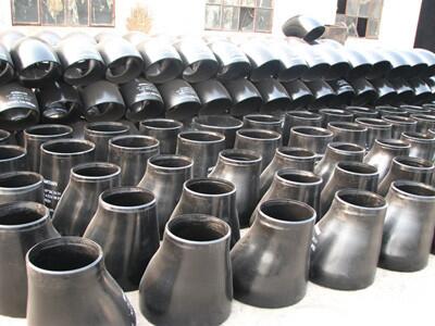
Pipe reducers are essential components in fluid delivery systems, connecting pipes of different diameters. Correct reducer size selection directly impacts system efficiency, safety, and cost. This guide provides a detailed dimension reference table and practical selection criteria to help you specify the right reducer for your application.
Below is the standard ANSI B16.9 reducer size chart, covering concentric and eccentric dimensions from NPS 3/4" to 24". Use this chart to match your required end diameters and length.
📥 [Download Reducer Dimensions Chart in mm (PDF)]
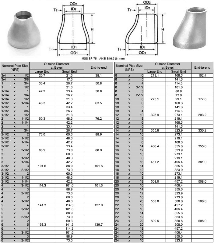
To correctly read the table above, here are the key size parameters you need to know.
1. NPS (Nominal Pipe Size)
This is the inch-based size designation used in ASME standards (e.g., 4", 6", 8"). In the table, NPS identifies the nominal size of each reducer end. It is the primary reference for matching reducers to standard pipes.
2. DN (Diameter Nominal)
This is the metric equivalent of NPS (e.g., DN100, DN150). DN and NPS refer to the same nominal size — they are just expressed in different units (4" = DN100, 6" = DN150). Most international tables show both for cross-reference.
3. Outside Diameter (OD / D1/D2)
This is the actual measured outside diameter of the reducer ends, shown in the table as "Outside Diameter at Bevel" for the Large End and Small End. For example, a 4" (DN100) reducer has an actual OD of 114.3 mm per ASME B16.9. This is the dimension you must match to your pipe's OD.
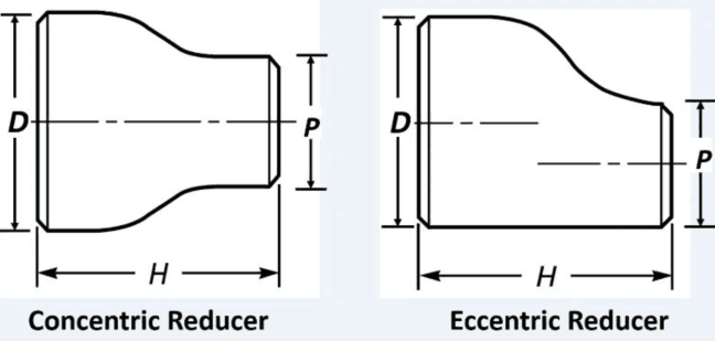
4. Length (H / End-to-End)
The overall distance from the large-end face to the small-end face. Standard lengths are defined by ASME B16.9 (shown in the "End-to-end" column). Special lengths can be customized for project-specific needs.
5. Wall Thickness (Sch / Schedule)
The wall thickness grade (Schedule) of a reducer must match the connecting pipe. Common grades include Sch10, Sch40, Sch80, STD, XS, Sch160, and XXS. A higher Sch number means a thicker wall and greater pressure capacity, but the actual pressure rating also depends on material, temperature, and the piping design code (e.g., ASME B31.3). For reducers, the large end and small end may have different wall thicknesses, matching the respective pipes.
Before consulting the dimension table, it is helpful to understand the key factors that determine the correct reducer size for your specific system.
| Fluid Type | Key Concern | Recommended Material |
|---|---|---|
| Water, oil, gas (non-corrosive) | General durability | Carbon steel (ASTM A234 WPB) |
| Acids, chemicals, seawater | Corrosion resistance | Stainless steel (ASTM A403 WP304/316L) |
| High-temperature steam, hot oil | Heat resistance | Alloy steel (WP11/WP22) |
| Slurries, viscous fluids | Abrasion & flow | Larger diameter, wear-resistant liner |
How to apply: Identify your fluid's corrosivity, temperature, and viscosity. Match these to the appropriate material grade before selecting dimensions.
● Tight spaces: Verify the reducer's total length (H dimension) against available clearance.
▶ For more details on selecting concentric and eccentric reducers, please refer to [Concentric Reducers vs. Eccentric Reducers: When to Use Which?].
Larger diameter reducers cost more upfront but reduce energy loss over time. Smaller diameters are cheaper initially but may increase pumping costs. In most cases, selecting the smallest diameter that meets your flow and pressure requirements offers the best balance of cost and performance. For standard water, oil, or gas services, carbon steel (A234 WPB) is the most cost-effective material choice.
When designing with reducers, the key is to match the reducer to the pipe schedule, design code, and installation conditions. Always match the reducer bore to the pipe bore to avoid turbulence and pressure drop. For pump suction lines, use an eccentric reducer with the flat side up to prevent air pockets. For horizontal liquid lines, use a bottom-flat eccentric reducer to allow drainage. Confirm the reducer size (NPS, length H, and end diameters) against the ANSI B16.9 table before finalizing your design.
Note for water pipe reducer sizes:
Common water pipe reducer sizes include 8x6, 6x4, 4x3, and 2x1.5. For water supply lines, carbon steel or stainless steel reducers are typically used, with wall thickness matching the pipe schedule. Contact us for specific water pipe reducer dimensions.
After reviewing these six factors, you should have a clear understanding of your required:
● Reducer type (concentric or eccentric)
● Material grade (carbon steel, stainless, or alloy)
● Wall thickness (Sch rating)
● End diameters (based on your upstream and downstream pipe sizes)
▶ [Link to your inquiry form or sample download page]
| Material | Common Grades | Typical Use |
|---|---|---|
| Carbon Steel | A234 WPB, A860 WPHY | General water, oil, gas |
| Stainless Steel | A403 WP304/316L | Corrosive, food, marine |
| Alloy Steel | A234 WP11/WP22 | High-temperature service |
| Low-Temp Steel | A420 WPL6 | Below -29°C applications |
● Pressing/Pushing: The most common seamless pipe fitting production process, using metal molds to expand or reduce the diameter of the pipe blank.
● Forging: Heating and forging a steel billet results in a dense internal structure and high mechanical strength, particularly suitable for high-pressure applications.
● Casting: Directly casting molten steel, suitable for manufacturing complex or large pipe fittings, but may contain casting defects such as porosity and sand holes.
● Welding (Rolling): Steel plates are rolled and then welded together, mainly used for manufacturing large-diameter pipe fittings.
4. Classification by Pressure Rating (Wall Thickness)
This represents the pressure rating that the pipe fitting can withstand, usually indicated by "Sch" (Schedule).
Common Grades: From Sch5s, Sch10s to Sch160, up to XXS (extra thick), there are approximately 17 grades.
Standard wall thickness: STD (standard) and XS (thickened) are the two most commonly used wall thickness grades in engineering.
5. Classification by manufacturing standards
Standards determine the dimensional series, geometric tolerances, and inspection requirements of pipe fittings, ensuring interchangeability.
International standards: The most commonly used is ASME B16.9 (American standard), and there are also EN 10253 (German/European standard), MSS SP-75 (Specification for High-Test Wrought Butt Welding Fittings), etc.
Chinese standards: GB/T 12459 (seamless pipe fittings) and GB/T 13401 (welded pipe fittings) are the core national standards.
Other industry standards: These also include standards from the Ministry of Chemical Industry (HG), the Ministry of Machinery Industry (JB), and the Ministry of Electric Power (GD), etc.
Q1. What is the difference between concentric reducers and eccentric reducers? How should I choose?
A: Concentric reducers: The centerlines are on a straight line, and the diameter change is symmetrical. They are typically used for:
a. Vertical pipes: This is the most common scenario, used to change the pipe diameter and allow for natural flow.
b. Horizontal gas/vapor pipes: Allows for easy drainage of condensate, preventing liquid accumulation.
Eccentric reducers: One side of the pipe wall is straight, and the centerlines do not coincide. They are typically used for horizontal liquid lines:
a. Horizontal Liquid Piping: This is the most important application. Using a "top-flat" installation prevents air pockets from forming at the bottom of the pipe; using a "bottom-flat" installation maintains a consistent bottom elevation for easier support.
b. Pump Inlet Piping: To prevent cavitation, a "top-flat" eccentric reducer is typically used to ensure no gas accumulates at the pump inlet.
c. Space Constraints: When piping needs to be installed close to a wall or floor.
Common mistake: Installing an eccentric reducer flat side down in liquid service is a frequent error that can lead to pump cavitation and premature failure.
Q2: What do "DN" and inches (NPS) mean on pipe reducers? How do I convert them?
A: DN (Diameter Nominal) and NPS (Nominal Pipe Size) refer to the same nominal size but use different units:
● DN is metric (e.g., DN100)
● NPS is inch-based (e.g., 4")
General correspondence: DN25 ≈ 1", DN100 ≈ 4", DN200 ≈ 8". However, these are nominal references, not exact conversions. For precise dimensions (especially outside diameter), always refer to the standard dimension table (ASME B16.9) rather than converting mathematically.
Q3. What is the order of marking the "larger end" and "smaller end" of a pipe reducer?
A: The order is crucial; incorrect marking can lead to installation failure. The industry standard is: Larger diameter × Smaller diameter. For example, a reducer connecting a DN200 pipe to a DN150 pipe should be marked as DN200×150 (or 8"×6").
Q4. When selecting a reducer, besides the diameter, what other parameters should be considered?
A: When selecting a reducer, confirm these five additional parameters:
a. Wall Thickness/Pressure Rating: Must match or exceed the pressure rating of the connected piping (e.g., Sch40, Sch80, PN16, Class 150). This directly affects pressure resistance.
b. Material: Must be compatible with the piping and fluid medium. Common materials include carbon steel (ASTM A234), stainless steel (304, 316L), and alloy steel.
c. Connection method: Welded, flanged, or threaded connection?
d. Applicable standard: Ensure the reducer conforms to the same standard as the pipe to guarantee dimensional interchangeability, such as ASME B16.9.
e. Center to end face length: For eccentric reducers, this dimension (especially the height of the "flat edge") is crucial for accurate installation and must be clearly stated on the drawings.
Q5: How should an eccentric reducer be oriented during installation?
A: For horizontal pipelines, orientation depends on the service medium:
● Liquid service (e.g., pump suction lines): Install with the flat side on top. This prevents air or vapor pockets that cause cavitation.
● Gas or vapor service: Install with the flat side on bottom. This prevents condensate pooling that can lead to water hammer or corrosion.
For vertical pipelines, concentric reducers are typically preferred — orientation is not a concern.
Every piping system has unique requirements. If you are unsure about any selection parameter, our engineering team can help you:
● Review your system specifications and recommend the optimal reducer size
● Provide material recommendations based on your fluid and temperature conditions
● Offer custom manufacturing for non-standard sizes or special lengths
▶ [Get a Quick Quote]
Understanding the external dimensions of reducer fittings and their selection points is of great significance for correct material selection and design. In actual engineering, factors such as flow demand, fluid properties, pressure requirements, temperature, space limitations and economic factors need to be considered comprehensively to select appropriate pipe reducers and ensure the safe and efficient operation of the piping system.
Related resources:
● Concentric Reducers vs. Eccentric Reducers: When to Use Which?
● Pipe Reducer Industry Applications
Related information
Copyright @2017 Hunan Standard Steel Co.,Ltd and Husteel Industry Group All Rights Reserved